Файл:Voyager spacecraft structure.jpg
Оригинален файл (800 × 1000 пиксела, големина на файла: 235 КБ, MIME-тип: image/jpeg)
| Този файл е от Общомедия и може да се използва от други проекти.
Следва информация за файла, достъпна през оригиналната му описателна страница. |
Резюме

| Описание |
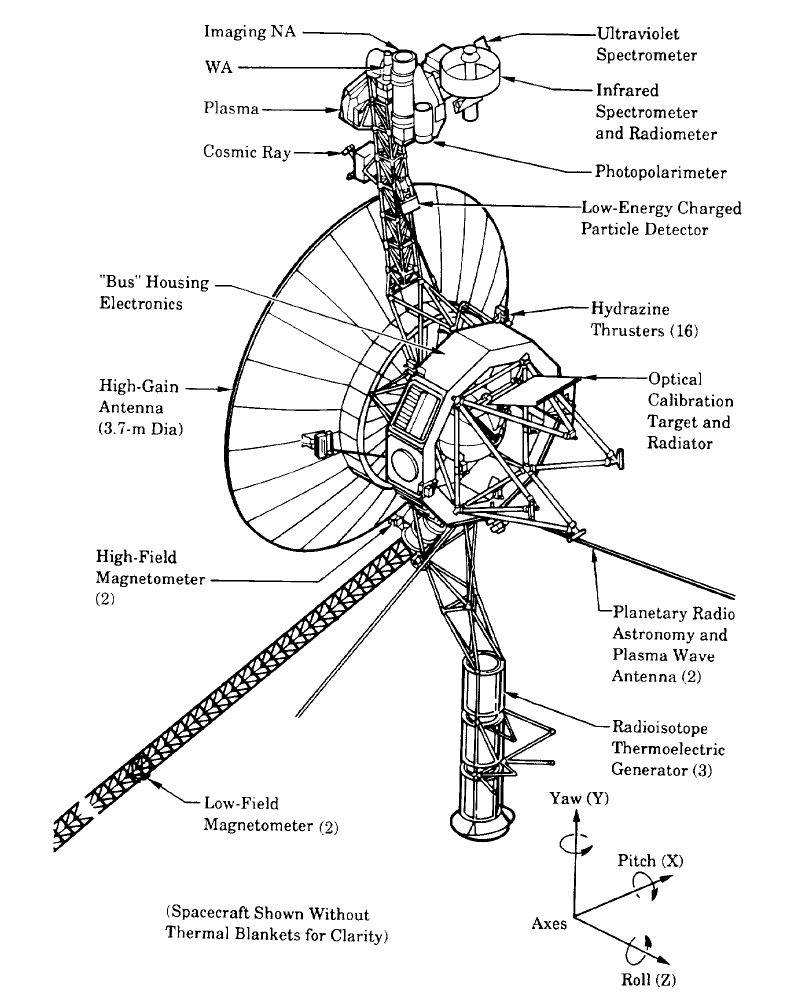
English: The Voyager spacecraft structure - schematic diagram.
The 3.7 metre diameter high-gain antenna (HGA) is attached to the hollow ten-sided polygonal electronics bus, with the spherical tank within containing hydrazine propulsion fuel. The Voyager Golden Record is attached to one of the bus sides. The angled square panel to the right is the optical calibration target and excess heat radiator. The three radioisotope thermoelectric generators (RTGs) are mounted end-to-end on the lower boom. The two planetary radio and plasma wave antenna extend diagonally downwards left and right. The 13 metre long Astromast tri-axial boom extends diagonally downwards left and holds the two low-field magnetometers (MAG); the high-field magnetometers remain close to the HGA. The instrument boom extending upwards holds, from bottom to top: the cosmic ray susbsystem (CRS) left, and Low-Energy Charged Particle (LECP) detector right; the Plasma Spectrometer (PLS) right; and the scan platform that rotates about a vertical axis. The scan platform comprises: the Infrared Interferometer Spectrometer (IRIS) (largest camera at top right); the Ultraviolet Spectrometer (UVS) just above the UVS; the two Imaging Science Subsystem (ISS) vidicon cameras to the left of the UVS; and the Photopolarimeter System (PPS) under the ISS. Suggested for English Wikipedia:alternative text for images: A space probe with squat cylindrical body and a large parabolic radio antenna dish pointing left, a three-element radioisotope thermoelectric generator on a boom extending down, and scientific instruments on a boom extending up. A disk is fixed to the body facing front left. A long tri-axial boom extends down left and two radio antenna extend down left and down right.Polski: Schemat konstrukcji sondy Voyager |
| Дата | |
| Източник | The Voyager Neptune Travel Guide |
| Автор | NASA |
| други версии |
Derivative works of this file: |
Лицензиране
| This file is in the public domain in the United States because it was solely created by NASA. NASA copyright policy states that "NASA material is not protected by copyright unless noted". (See Template:PD-USGov, NASA copyright policy page or JPL Image Use Policy.) | ||
 |
Warnings:
|
История на файла
Избирането на дата/час ще покаже как е изглеждал файлът към онзи момент.
| Дата/Час | Миникартинка | Размер | Потребител | Коментар | |
|---|---|---|---|---|---|
| текуща | 05:10, 4 декември 2009 | | 800 × 1000 (235 КБ) | Camilo Sanchez | Reverted to version as of 19:07, 24 July 2008 |
| 05:07, 4 декември 2009 |  | 744 × 1052 (1023 КБ) | Camilo Sanchez | Raster to vector version | |
| 19:07, 24 юли 2008 |  | 800 × 1000 (235 КБ) | Mirecki | {{Information |Description={{en|1=The Voyager spacecraft structure - schematic diagram}} {{pl|1=Schemat konstrukcji sondy Voyager}} |Source=The Voyager Neptune Travel Guide |Author=NASA |Date=June 1, 1989 |Permission= |other_versions= }} {{ImageUpload|fu |
Използване на файла
Следната страница използва следния файл:
Глобално използване на файл
Този файл се използва от следните други уикита:
- Употреба в da.wikipedia.org
- Употреба в en.wikipedia.org
- Употреба в fi.wikipedia.org
- Употреба в it.wikipedia.org
- Употреба в ja.wikipedia.org
- Употреба в ko.wikipedia.org
- Употреба в nl.wikipedia.org
- Употреба в sr.wikipedia.org
- Употреба в zh.wikipedia.org